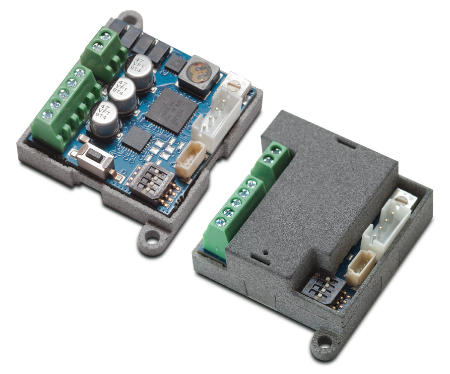
STEPPER GEARMOTOR DRIVER
MM003AT/21-22
The step-motor is a synchronous electric motor with pulsed direct current and brushless electronic control which can divide its rotation into a large number of steps. Unlike brush DC motors, the position of the motor can be accurately controlled without an encoder (feedback). It is extremely important to choose the correct size and type of motor to suit the application. The use of a step-motor requires a careful preliminary analysis of the operating conditions in order to correctly characterise the system.
Since control electronics are required to ensure an optimal use of step motors, Micro Motors has developed a dedicated driver for its product range, which offers the possibility of using the motors in a simple and versatile way.


Technical Features:
- POWER SUPPLY: from 12 to 30Vdc - from 12 to 24Vac
- SETTING CURRENT: 160mA or 330mA
- OPERATING MODE: as a step-motor (STEP/DIR) or as a brush motor simulation
- DIMENSIONS: 33 x 33 x 14 mm
- WEIGHT: approx. 10g
Overview:

- A = Power input terminal
- B = Control signal input terminal
- C = Speed/acceleration trimmer
- D = Motor connection
- E = DIP switch program configuration
- F = Service button
Connections:
- 1-2 = Power input +/-, for more details see “programs” section
- 3 = Step pulse input (5-30V, ref. program 3)
- 4 = Input for CW/CCW rotation (connect to GND to change the rotation direction, ref. Programs 3,4,5 and 6)
- 5 = Speed control by voltage input (1-5V or 2-10V program ref. 4 and 5)
- 6 = Speed control by current input (4-20mA ref. Program 6)
- 7 = GND reference point of the signals described above

| Selectable Programs | |
|---|---|
| PROG. 1 | BRUSH MOTOR SIMULATION WITH DC DRIVER INPUT, CW/CCW ROTATION ACCORDING TO POWER SUPPLY POLARITY. |
| PROG. 2 | BRUSH MOTOR SIMULATION WITH AC/DC DRIVER INPUT AND FIXED CW/CCW ROTATION. |
| PROG. 3 | STEPPER WITH AC/DC DRIVER INPUT AND STEP/DIR CONTROL. |
| PROG. 4 | BRUSH MOTOR SIMULATION WITH AC/DC DRIVER INPUT WITH SPEED (5V) AND ACCELERATION/DECELERATION CONTROL. |
| PROG. 5 | BRUSH MOTOR SIMULATION WITH AC/DC DRIVER INPUT WITH SPEED (10V) AND ACCELERATION/DECELERATION CONTROL. |
| PROG. 6 | BRUSH MOTOR SIMULATION WITH AC/DC DRIVER INPUT WITH SPEED (4-20mA) AND ACCELERATION/DECELERATION CONTROL. |
| PROG. 7 | MAXIMUM CURRENT SETTING 160 or 330mA. |
PROGRAM SELECTION (DIP Switch “E”)
DIP switch: 1 = OFF 2 = OFF 3 = OFF 4 = (see program 7)
In this configuration the motor acts like a brush motor whose CW/CCW rotation depends on the power supply polarity applied to terminals 1 and 2. Trimmer “C” sets the speed. Motor torque varies according to supply voltage and speed.

DIP switch: 1 = ON 2 = OFF 3 = OFF 4 = (see program 7)
In this configuration the motor acts like a brush motor whose CW/CCW rotation is not determined by the power supply polarity, but by the position of the dipswitches 1 and 2. Trimmer “C” sets the speed. The driver can be powered in either AC or DC mode (terminals 1 and 2).

DIP switch: 1 = OFF 2 = ON 3 = OFF 4 = (see program 7)
As the previous configuration but with the opposite direction of rotation.

DIP switch: 1 = ON 2 = ON 3 = OFF 4 = (see program 7)
In this configuration the motor acts like a step-motor. The driver can be powered either in AC or DC mode (terminals 1 and 2). A square wave signal must be applied to terminal 3 which determines the speed of the motor (from 5 to 30V), while terminal 4 determines the CW/CCW rotation (connect or disconnect to GND to reverse rotation).

DIP switch: 1 = OFF 2 = OFF 3 = ON 4 = (see program 7)
In this configuration the motor acts like a brush motor whose speed is determined by the voltage supplied on terminal 5 (from 1 to 5V), while terminal 4 determines the CW/CCW rotation (connect or disconnect to GND to reverse direction). The drive can be powered either in AC or DC mode (terminals 1 and 2). Trimmer “C” sets the acceleration and deceleration.

DIP switch: 1 = ON 2 = OFF 3 = ON 4 = (see program 7)
In this configuration the motor acts like a brush motor whose speed is determined by the voltage supplied on terminal 5 (from 2 to 10V), while terminal 4 determines the CW/CCW rotation (connect or disconnect to GND to reverse direction). The driver can be powered either in AC or DC mode (terminals 1 and 2). Trimmer “C” sets the acceleration and deceleration.

DIP switch: 1 = OFF 2 = ON 3 = ON 4 = (see program 7)
In this configuration the motor acts like a brush motor whose speed is determined by the current supplied on terminal 6 (from 4 to 20mA), while terminal 4 determines the CW/CCW rotation (connect or disconnect to GND to reverse direction). The driver can be powered either in AC or DC mode (terminals 1 and 2). Trimmer “C” sets the acceleration and deceleration.

The maximum motor current is set with dip switch 4.
DIP switch: 1 = (x) 2 = (x) 3 = (x) 4 = OFF
The maximum motor current is set at 330mA.
DIP switch: 1 = (x) 2 = (x) 3 = (x) 4 = ON
The maximum motor current is set at 160mA.
